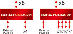
| Upstream PCIe interface |
- 8-lane PCI Express
- PCIe Gen 1 (2.5GT/s)
- PCIe Gen 2 (5.0GT/s)
|
| Downstream PCIe interface |
- One 38pin iPass™ (0.8mm pitch) compatible I/O Connector
- Scalability up to 10Gb/s
- PCIe Gen I – 2.5Gb/s
- PCIe Gen II – 5.0Gb/s
- Durability - 250 cycles
- Fully shielded to provide maximum EMI/RFI protection
- Guide to system bezel gasket
- Cable plug gasket to front face of Guide
- First mate, last break
- RoHS compliant
- Two IOI Proprietary Dual-lane Internal PCIe Ports
(PCIe-1~2)
- 10X2_19pin Header (Pitch=2.0mm)
- 2-lane PCIe
- Each Dual-lane Internal PCIe Port
- PCIe Gen 1 (2.5GT/s)
- PCIe Gen 2 (5.0GT/s)
|
| Key Features |
- Standards Compliant
- PCI Express Base Specification r2.0 (Backwards compatible with PCIe r1.0a/1.1)
- PCI Power Management Spec r1.2
- Microsoft Vista Compliant
- Supports Access Control Services
- Dynamic link-width control
- Dynamic SerDes Speed Control
- High Performance
- Non-blocking internal architecture
- Full line rate on all ports
- Cut-Thru latency: 140ns
- Maximum Payload Size - 2,048 bytes
- Read Pacing (intelligent bandwidth allocation)
- Dual Cast
- Dynamic Buffer Pool Architecture for faster credit updates
- PCI Express Power Management
- Link power management states: L0, L0s, L1, L2/L3 Ready, and L3 (with Vaux not supported)
- Device power management states: D0 and D3hot
- Active State Power Management (ASPM)
- Quality of Service (QoS)
- Two Virtual Channels (VC) per port
- Eight Traffic Classes per port
- Weighted Round-Robin Port & VC Arbitration
|
Lane Status LEDs
- Blink: Gen 1 speed
- Solid: Gen 2 speed
|
- Upstream Lane Status LEDs
- ULED1: Upstream x1 Status LED
- ULED4: Upstream x4 Status LED
- ULED8: Upstream x8 Status LED
- Downstream Lane Status LEDs
- J1LEDL8: Downstream Lane 8 Status LED
- J1LEDL9: Downstream Lane 9 Status LED
- J1LEDL10: Downstream Lane 10 Status LED
- J1LEDL11: Downstream Lane 11 Status LED
- PCIe-1L12: Downstream Lane 12 Status LED
- PCIe-1L13: Downstream Lane 13 Status LED
- PCIe-2L14: Downstream Lane 14 Status LED
- PCIe-2L15: Downstream Lane 15 Status LED
|
Jumper JP3
(PCIe Port Configuration) |
|
| Switch |
- Non-Transparent Mode
- ON: Enable
- OFF: Disable (default)
- Select Upstream NT Port
- ON: Port 1 (default)
- OFF: Port 3
- Link Upconfigure Timer enable
(For Gen 1 devices that do not ignore the Gen 2 Upconfigure bits during the Link Training sequence)
- ON: Enable
- OFF: Disable (default)
- PCIe Lane Config
- ON: PCIe Gen1 (2.5Gb/s)
- OFF: PCIe Gen2 (5Gb/s) (default)
|
| Computer Platform Requirements |
Desktop computer equipped with a PCIe 1.0/2.0 x8, x16 slot |
