| PCI Express |
- Standards compliant
- Compliant with PCI Express Base Specification Revision 2.1
- Compliant with PCI Express CEM Specification Revision 2.0
- Compliant with PCI-to-PCI Bridge Architecture Specification Revision 1.2
- Compliant with Advanced Configuration Power Interface (ACPI) Specification
- PCI Power Management Spec r1.2
- PCI Express Power Management
- Link power management states: L0, L0s, L1, L2/L3 Ready, and L3
- Device states: D0 and D3hot
- Active state power management for L0s and L1 states
- Port Arbitration Round Robin (RR) and Weighted RR and Time-based Weighted RR
- Extended Virtual Channel capability
- Two Virtual Channels (VC) and Eight Traffic Class (TC) support
- Independent TC/VC mapping for each port
- Provides VC arbitration selection: Strict Priority, Round Robin (RR) and Programmable Weighted Round-Robin
- Supports Isochronous Traffic
- Isochronous traffic class mapped to VC1 only
- Strict time based credit policing
- Supports “Cut-through”(Default) as well as “Store and Forward” mode for switching packets
- Peer-to-peer switching between any two downstream ports
- Supports up to 512-byte maximum payload size (setting to 256-byte)
- Enhanced Features
- 150ns typical latency for packet running through switch without blocking
- Supports Access Control Service (ACS) for peer-to-peer traffic
- Supports Address Translation (AT) packet for SR-IOV application
- Supports OBFF and LTR
|
| USB Features |
- Compliant with USB 3.0 Specification Revision 1.0
- Compliant with Extensible Host Controller Interface (xHCI) Specification revision 1.0
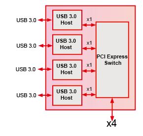
- 4 downstream USB ports support SS/HS/FS/LS data rates (5Gbps/480Mbps/12Mbps/1.5Mbps)
- Supports UASP (USB Attached SCSI Protocol)
- Supports xHCI debug capability
- Support for Ultra High-performance isochronous applications
- Support for Latency Tolerance Tolerance Messaging (USB)
|
| Advanced Power Saving |
- Support all USB 3.0 Power States: U0, U1, U2 and U3
- Support USB 2.0 Link Power management (LPM)
- PCIe Active State Power Management (ASPM) L0s and L1
|
| USB3 cable lock mechanism |
- Provides the threaded holes for the jack-screws of USB 3.0 A Plug w/Jackscrew lock Cable
- IOI Standard cable port lock mechanism

|
USB Bus Power Input |
-
12V Step-Down to 5V from either PCIe 12V or Power Connector 12V (ATA 4-pin or SATA 15-pin)
The USB Bus power (5V) are step-down from 12V and the
12V input might from either PCIe Edge Connector or
Auxiliary Power Connectors (J1 & J2).
Note:
If the PCIe Slot can’t supply 12V current high enough then you have to
attach the Auxiliary Power from either J1 (ATA 4-pin) or J2 (SATA 15-pin).
|

