ES2DSATA10-SI is SATA to dual SATA RAID Bridge Board
ES2DSATA10-SI is a selectable hardware RAID Bridge Board with two SATA ports. A true hardware solution, ES2DSATA10-SI requires no software to be installed on your machine.
You can configure the ES2DSATA10-SI to use the following Storage Policies to map the appliance's physical hard drives to virtual drives that are visible to the host computer.
- BIG (Concatenation)
- JBOD (Just a Bunch Of Disks)
- FAST (RAID 0)
- SAFE (RAID 1)
- SAFE33 (1/3 to SAFE mode and 2/3 to BIG mode)
- SAFE50 (1/2 to SAFE mode and 1/2 to BIG mode)
- GUI (Use the SteelVine Manager GUI to configure the Storage Policy)
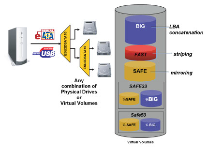
BIG:
The BIG storage policy concatenates a series of physical hard
drives as a single large volume; resulting in a seamless expansion of
virtual volumes beyond the physical limitations of singularly connected
hard drives. The BIG storage policy delivers maximum storage space without
a single large capacity and costly hard drive. Any node within a cascaded
configuration can be set to BIG.
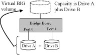 |
BIG storage policy sample configuration
|
It is also possible to create a BIG volume using only a single hard disk drive connected to Port 0, and then increase the storage capacity of the volume later by adding another hard disk drive (or another ES2DSATA10-SI with at least one hard disk drive) to Port 1 and pressing the Mode Change push-button. The new disk blocks of Port 1 will be concatenated to the end of the disk blocks of Port 0, and any data that is stored on the existing BIG volume will be preserved. However, it is not possible to expand an existing BIG volume by adding another hard disk drive to Port 0 and still preserve any existing data on that volume.
JBOD (Just a Bunch Of Disks):
The JBOD (Just a Bunch of Disks) storage policy enables each hard drive
to be seen separately as one drive. When using a SATA host controller,
JBOD should only be used if the SATA host controller provides Port Multiplier
(PM) support. If a host is not PM-aware, only a single drive is presented
(drive 0). No such limitation if using a USB host connection.
JBOD storage policy is available for a standalone (non-cascaded) ES2DSATA10-SI
or the top-level node of a cascaded configuration, but not for subordinate
nodes. Even though you can use the rotary switch to select JBOD mode for
any node in a cascaded configuration, only the first JBOD volume of any
subordinate node is detected by your host. Therefore, selecting JBOD mode
for any subordinate node is not recommended.
In a JBOD configuration, the ES2DSATA10-SI directly exposes each physical
drive.
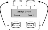 |
JBOD storage policy sample configuration |
FAST (Striping):
The FAST storage policy distributes access across all hard disks, also
called striping (equivalent to RAID 0). FAST presents the best data speed
but no data redundancy. FAST storage policy accelerates hard disk operating
speed by using many disks in parallel. Hard drive data segments are written
to different disks simultaneously which increases performance while sacrificing
data redundancy.
To implement the FAST storage policy, the ES2DSATA10-SI creates a single
virtual volume that is striped across both hard drives, with a storage
capacity that is equal to the sum of both hard disk drives.
It is possible to set any node within a cascaded configuration to FAST,
although there is no performance benefit when using multiple layers of
striping.
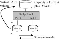 |
FAST storage policy sample configuration |
SAFE (Mirroring):
The SAFE storage policy stores all data in duplicate on separate drives
to protect against data loss due to drive failure. One drive mirrors the
other at all times, equivalent to RAID 1. Every write operation goes to
both drives. SAFE provides the highest level of data protection for critical
data that you cannot afford to lose if a hard drive fails, but halves
the amount of storage capacity because all data must be stored twice.
The resulting storage capacity of the virtual SAFE volume will be equivalent
to the size of one hard drive (if both drives are the same) or the smaller
of the two drives (if they are different).
If one drive fails, the SAFE volume is still usable, but it is in a vulnerable
state because its mirrored hard drive is inaccessible. When the offline
drive comes back online, the appliance begins a rebuild process immediately
to restore data redundancy. A message box appears in the GUI to notify
you that a rebuild is in progress.
Although the volume remains available during the rebuild process, the
volume is susceptible to data loss through damage to the remaining drive
until redundancy is restored at the end of the rebuild and verification
process. Host access takes precedence over the rebuild process. If you
continue to use the SAFE volume during the rebuild, the rebuild process
will take a longer time to complete, and the host data transfer performance
will also be affected.
Any node within a cascaded configuration can be set to SAFE, but it is
more efficient to use the SAFE policy at the lowest possible level within
the hierarchy.
It is also possible to create a SAFE volume using one hard disk drive
connected to Port 0 of the ES2DSATA10-SI, although no mirroring will occur
until a second hard disk drive is connected to Port 1. With only one hard
disk drive connected, the SAFE volume will be available, although no data
protection will be provided until a second hard disk drive is connected.
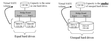 |
| SAFE storage policy sample configuration |
SAFE 33:
The SAFE33 storage policy creates two virtual volumes; one SAFE volume
and one BIG volume, and should be used when you need the high reliability
for some of your data (with the added overhead of mirroring) but you don’t
need high reliability for the remainder of your data. SAFE33 reduces the
cost of additional hard drives in operations where non-critical data could
be lost without severe consequences.
SAFE33 uses a SAFE volume that is mirrored across two hard drives to protect
your critical data in the event a hard drive failure. If one drive fails
the SAFE volume is retrievable although the BIG volume is not. When you
replace the failed drive, the SAFE volume is automatically rebuilt on
to the replacement drive.
For example, if you are using a video editing application that stores
the primary source data and also uses some temporary storage for editing,
you need protected storage that is offered by SAFE for the primary source
data, but you do not need protected storage for the temporary data. Therefore,
the combination of SAFE and BIG would be the most efficient utilization
of your available storage capacity. If either hard drive fails the primary
data stored on the SAFE volume would still be available whereas the temporary
data stored on the BIG volume would be lost.
The size of the SAFE volume of a SAFE33 policy will be one-third of the
size of one hard drive (if they are equal) or one-third of the size of
the smaller (if they are not equal.) The size of the BIG volume will be
the combination of all remaining capacities.
| Example: In Figure below, assume that Drives A and B are 300 GB each. When the SAFE33 Storage Policy is selected, the resulting virtual volumes will include SAFE volume of 100 GB (1/3 of 300 GB) and a BIG volume of 400 GB (the remaining capacity after allocating 100 GB from each of the hard drives). |
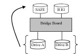 |
| SAFE33 storage policy sample configuration
|
SAFE 50:
The SAFE50 storage policy creates two virtual volumes; one SAFE volume
and one BIG volume, and should be used when you need the high reliability
for some of your data (with the added overhead of mirroring) but you don’t
need high reliability for the remainder of your data. SAFE50 reduces the
cost of additional hard drives in operations where non-critical data could
be lost without severe consequences.
SAFE50 uses a SAFE volume that is mirrored across two hard drives to protect
your critical data in the event a hard drive failure. If one drive fails
the SAFE volume is retrievable although the BIG volume is not. When you
replace the failed drive, the SAFE volume is automatically rebuilt on
to the replacement drive.
For example, if you are using a video editing application that stores
the primary source data and also uses some temporary storage for editing,
you need protected storage that is offered by SAFE for the primary source
data, but you do not need protected storage for the temporary data. Therefore,
the combination of SAFE and BIG would be the most efficient utilization
of your
available storage capacity. If either hard drive fails the primary data
stored on the SAFE volume would still be available whereas the temporary
data stored on the BIG volume would be lost.
The size of the SAFE volume of a SAFE50 policy will be one-half of the
size of one hard drive (if they are equal) or one-half of the size of
the smaller (if they are not equal). The size of the BIG volume will be
the combination of all remaining capacities.
| Example: In Figure below, assume that Drives A and B are 300 GB each. When the SAFE50 Storage Policy is selected, the resulting virtual volumes will include SAFE volume of 150 GB (1/2 of 300 GB) and a BIG volume of 300 GB (the remaining capacity after allocating 150 GB from each of the hard drives). |
 |
SAFE50 storage policy sample configuration |
Note:
When using a SATA host connection, you must have a PM (Port Multiplier)
aware host adapter when using SAFE33 (or SAFE50) on the top level node
of a cascaded configuration so that ALL volumes can be detected by the
host. If your SATA host adaptor is not PM aware, then ONLY the SAFE volume
will be detected and the BIG volume will not be accessible. No such limitation
exists when using a USB host connection.
For subordinate nodes in a cascaded configuration, it is possible to configure
a SAFE33 (or SAFE50)storage policy, although you will only see the SAFE
volume from that node. Therefore, the SAFE33 (or SAFE50) storage policy
should only be used at the top-level node of a cascaded configuration.
In this mode, the Schedule/Verify option
is enabled